Beacon IW3HVB/B
I had my hands on a GPSDO from Leo Bodnar in UK, to be used as 10 MHz reference oscillator for the transverters and the radios in my shack, and I found out that the phase noise of that little oscillator is actually quite good, so I thought to build a beacon for the 144 MHz band to be installed on one of the mountains overlooking the Pianura Padana in northern Italy. A beacon in that position had good chances to cover down to Puglia in summer, when the adriatic sea allows some ducting propagation on VHF and Up bands.
So I started to think on how to build something with it, and started digging on the net for bits and pieces useful to the project. It is incredible how many ready to plug in modules you can find nowadays for a very cheap price.
Given that A1A aka CW was going to be the mode of choiche, I started to sort out how to do the Keying, not a straightforward task to be done at the final frequency. The Programmable oscillator was going to be set directly at the Beacon Frequency (144.437 MHz), so all the switching had to be done in VHF.
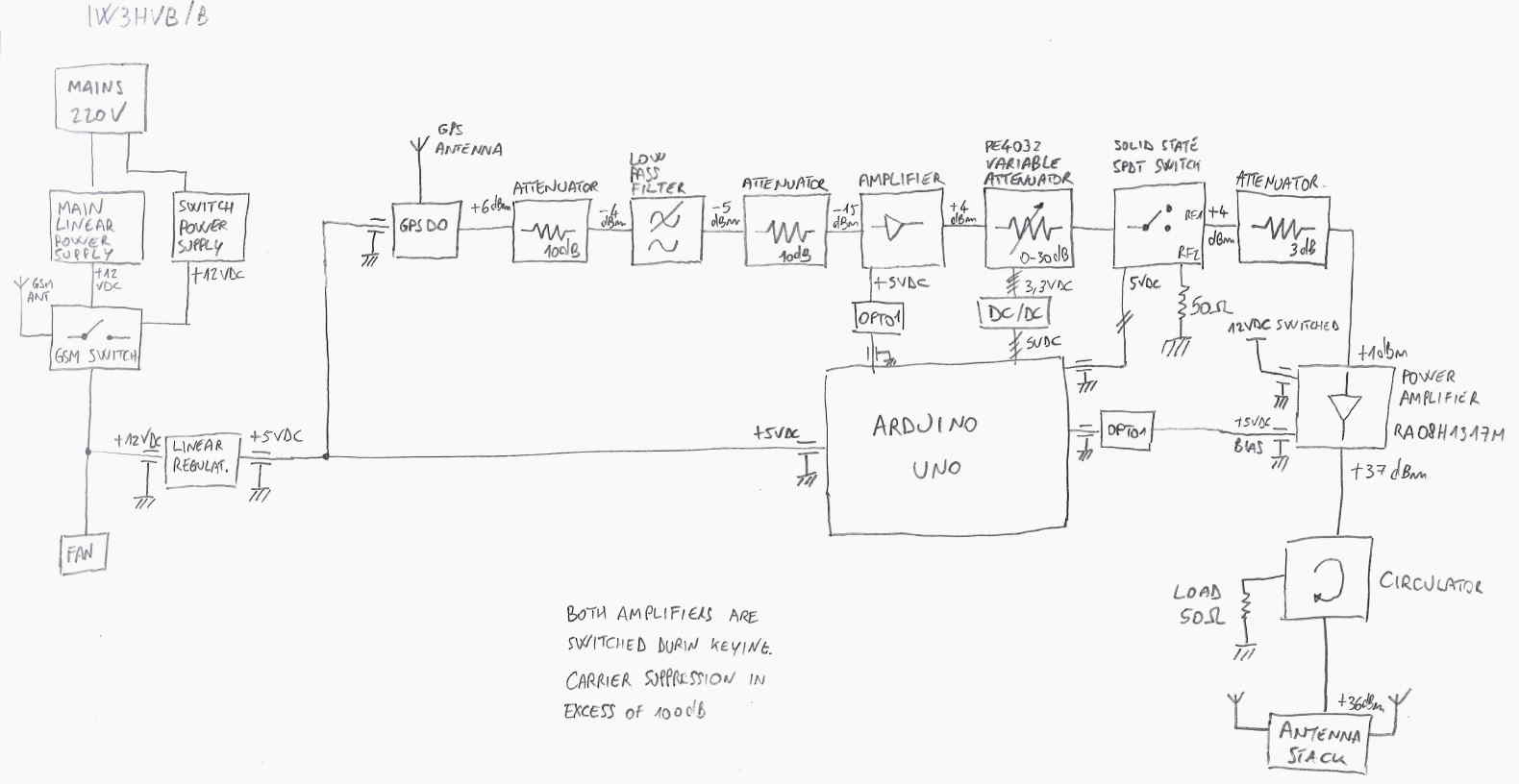
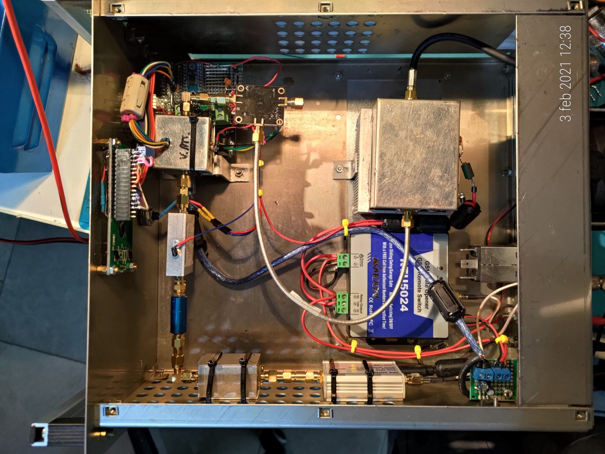
Let’s have a look to the diagram:
The power supply is switched via a GSM switch, compulsory here in Italy for this kind of automatic transmitter, when not attended.
The GPS disciplined oscillator generates a square wave with a +6dB amplitude (this is changeable via software if needed).
There is a low pass network and a first stage amplifier.
This amplifier is a LNA from Amazon, with milled case, 0-4 GHz 1.6 NF declared. Gives around 20 dB of gain at 144 MHz.
Following the first stage there is another interesting device found on Amazon, a variable 6 bits driven attenuator (based on the PE4032 chip from Peregrine Semiconductors), that can go from 0 to 31.5 dB. When I saw this I immediately started to think about a side feature that is missing in all the VHF & Up beacon I have listened to in the past few years: A beacon that changes power level. Drive the attenuator with an Arduino microcontroller is not that difficult, It is just a matter to write the code following the device truth table, but we will dig into this later looking at the code.
After the programmable attenuator we find a solid state SPDT switch. This also comes from Amazon (TSK!) and is fast enough to switch between ports without generating key clicks. It is weirdly driven with a 2 bit port, so 01 for port A and 10 for port B. Two Outputs from the Arduino stolen just for that.
After a level adjust we come to the final stage, a well known project from G4DDK as 8W PA for the Anglian Transverter. At 5W output linearity is good and without bias it is a good low level 30 dB attenuator.
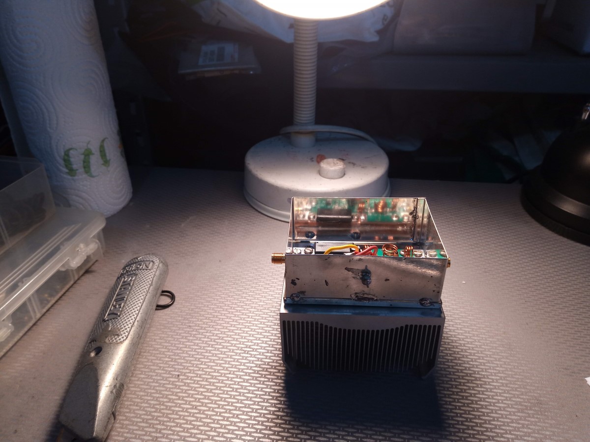
Given that the antennas were going to be installed at 1100 mtrs a.s.l. I decided to add a circulator, based on a TDK Hexalator, which ensures half a dB of loss and keeps any potential antenna problem out of the PA module.
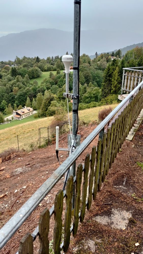
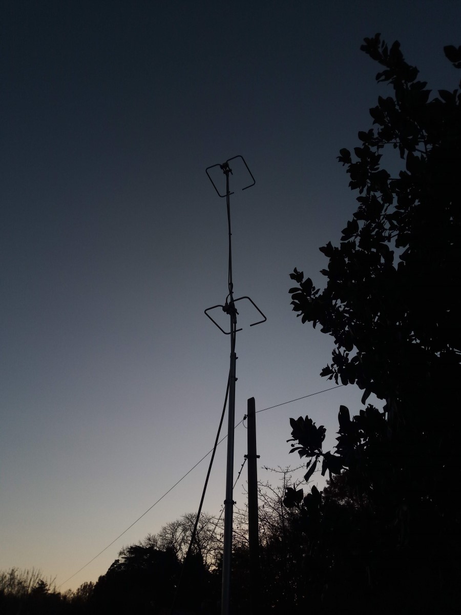
As Antenna I went for a 2 HO Loop stack from M2, courtesy of Davide IW3IDX.
The logic heart of the Beacon is an Arduino Uno microcontroller, which uses the well known CW libraries to key the carrier.
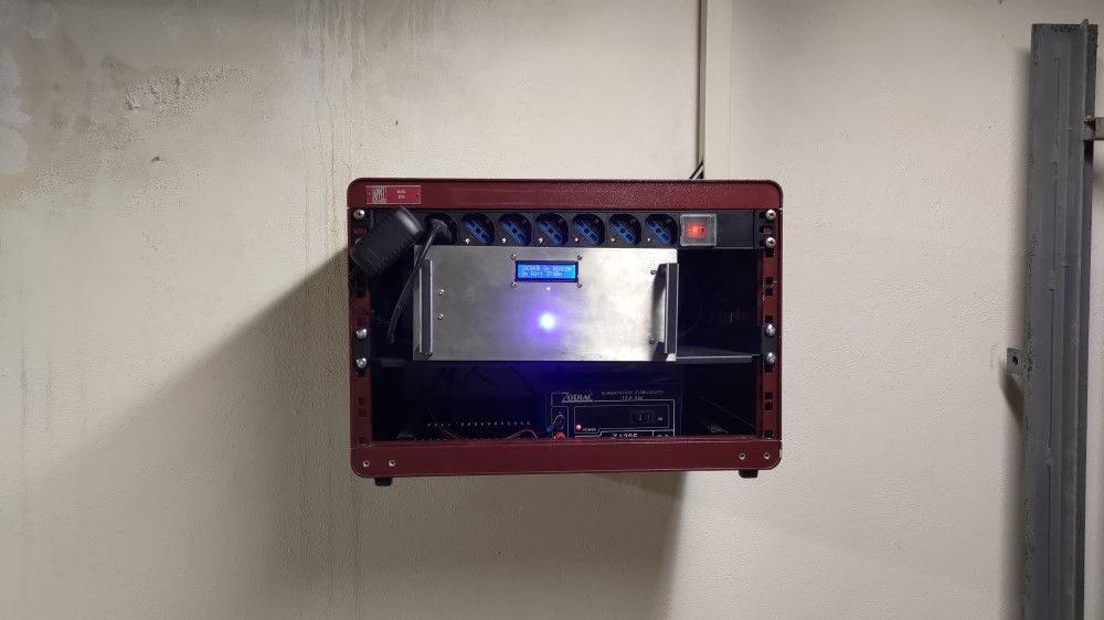
A local display is used to have a clue about the output power.
The message of the Beacon, in compliance with IARU Reg 1 beacon rules is:
VVV IW3HVB/B JN65AW
followed by the Output power in dBm that is transmitted at the moment so, for the first minute:
VVV IW3HVB/B JN65AW 37 dBm then carrier for around 30 sec.
On the second minute:
VVV IW3HVB/B JN65AW 27 dBm then carrier for around 30 sec.
VVV IW3HVB/B JN65AW 17 dBm then carrier for around 30 sec.
VVV IW3HVB/B JN65AW 7 dBm then carrier for around 30 sec.
then, back again at 37 dBm.
The beacon has 4 power levels, useful to check an S-Meter, or to give some hints about propagation when the signals are faint.
Problems encountered during testing, and solutions/workaround used to solve them:
The original prototype was a little different from what it has become, since I had to make some modifications to solve a few problems encountered during testing.
There are 3 main problem areas:
Harmonic Content, Spurious Content, Carrier Suppression
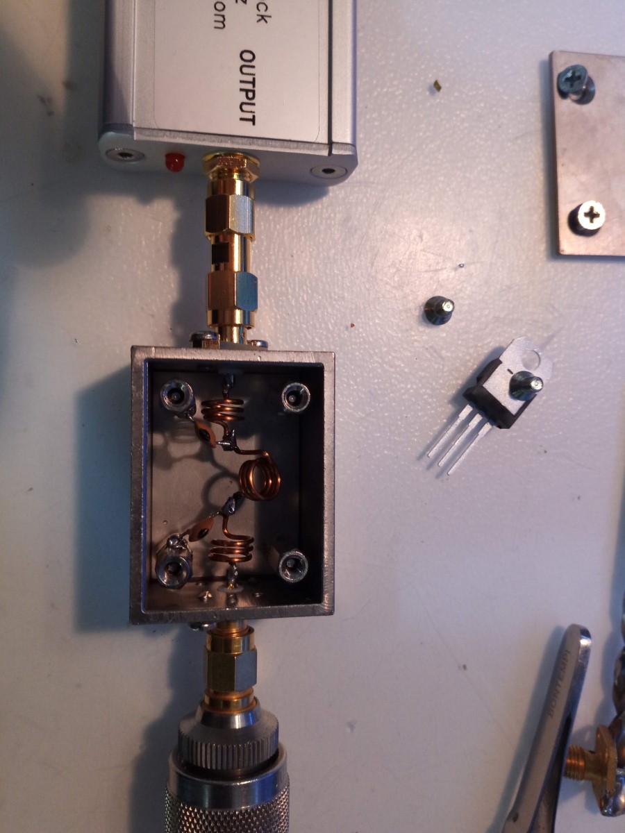
The first issue was about the oscillator itself: the squared waveform albeight good in close-in phase noise, had a vast harmonic content. The LPF stage after the final power amplifier, verified in a few tests, was not enough, so I had to add another Low Pass Filter right after the LO in order to optimize the frequency response.
With the second filter the harmonics are well within FCC requested levels. Please note that the first LPF sits in between two 10 dB attenuators. Those are there not only to keep levels within linearity range of the amplifier stages, but also to stabilize the impedence seen by the filter, further improving the frequency response.
Another common problem often found in beacons is an insufficient carrier suppression during keying. Containing leakage between the different stages, and using the highest possible isolation during off periods are paramount to avoid carrier residue.
In this case I had to do some tweaking. I initially hoped that switching the Final Power Amplifier Bias along with the solid state switch would have been enough. I was wrong. I had to insert the First Power Amplifier as a driver, and switch it along the rest to be able to get the carrier disappear completely. In the end the Carrier suppression is in excess of 100 dB.
The most difficult part by the way concerned some spurious emission, up to -30 dBc, that gave me some headache for quite some time. Tracing this kind of problem can be hard, expecially when you work in a lab where leakage from the stages can fool you, letting you believe that some signals are fed to the antenna when they are not.
Anyway, in the end lots of problems came from the main switching power supply (what else?), and from a DC/DC power module used to derive the 5V directly from the 12V rail.
This is the reason why now the power supply is linear and it is kept outside of the box, as well as a good old 7805 take care of the 5V supply, and the GSM switch is powered via a separate power supply.
In the end, when you think that you used enough shielding, it is not enough. When all the power rails are uncoupled by capacitors and ferrite beads or toroids, it may still be not enough. Ensuring linearity within the signal chain is not enough. Every small ripple or switching noise that can find a way to couple with the carrier will show itself. After all the tweaks I made the residual spurii are well under 90 dBc, and not audible when not in the immediate vicinity of the Beacon Box.
The code:
======================================================================
/*
ArduBeacon by FVZ Vers 0.1
*/
define WPM 15
define pinPTT1 13
define pinPTT2 12
define pinPTT3 11
define pinPTT4 10
define pinPTT5 9
define pinAtt1 A0
define pinAtt2 A1
define pinAtt3 A2
define pinAtt4 A3
define pinAtt5 A4
define pinAtt6 A5
define DEBUG 0
// Delay
const int delayDot = (1200 / WPM);
const int delayDash = (3 * 1200 / WPM);
const int delayChar = (2 * 1200 / WPM);
const int delayWord = (8 * 1200 / WPM);
// Morse table
byte morseLookup[] = {
//Letters
B01000001, B10001000, B10001010, B01100100, B00100000, B10000010,
B01100110, B10000000, B01000000, B10000111, B01100101, B10000100,
B01000011, B01000010, B01100111, B10000110, B10001101, B01100010,
B01100000, B00100001, B01100001, B10000001, B01100011, B10001001,
B10001011, B10001100,
//Numbers
B10111111, B10101111, B10100111, B10100011, B10100001, B10100000,
B10110000, B10111000, B10111100, B10111110, B10111110,
//Slash
B10110010,
//Dot
B11010101,
};
void setup()
{
if (DEBUG) {
Serial.begin(9600);
}
pinMode (pinPTT1, OUTPUT);
pinMode (pinPTT2, OUTPUT);
pinMode (pinPTT3, OUTPUT);
pinMode (pinPTT4, OUTPUT);
pinMode (pinPTT5, OUTPUT);
pinMode (pinAtt1, OUTPUT);
pinMode (pinAtt2, OUTPUT);
pinMode (pinAtt3, OUTPUT);
pinMode (pinAtt4, OUTPUT);
pinMode (pinAtt5, OUTPUT);
pinMode (pinAtt6, OUTPUT);
delay (10000);
}
void loop() {
setAttenuator (0);
transmitString (“VVV IW3HVB/B JN65AW 37DBM”);
ptt_delay (40, 1);
setAttenuator (10);
transmitString (“VVV IW3HVB/B JN65AW 27DBM”);
ptt_delay (40, 1);
setAttenuator (20);
transmitString (“VVV IW3HVB/B JN65AW 17DBM”);
ptt_delay (40, 1);
setAttenuator (30);
transmitString (“VVV IW3HVB/B JN65AW 7DBM”);
ptt_delay (40, 1);
}
// p_on secondi on – p_off Secondi off
void ptt_delay (unsigned long p_on, unsigned long p_off) {
ptt (1);
delay (p_on * 1000);
ptt(0);
delay (p_off * 1000);
}
void ptt ( int ptt) {
switch (ptt) {
case 0:
digitalWrite (pinPTT1, LOW);
digitalWrite (pinPTT3, LOW);
digitalWrite (pinPTT4, LOW);
digitalWrite (pinPTT5, LOW);
digitalWrite (pinPTT2, HIGH);
break;
case 1:
digitalWrite (pinPTT1, HIGH);
digitalWrite (pinPTT3, HIGH);
digitalWrite (pinPTT4, HIGH);
digitalWrite (pinPTT5, HIGH);
digitalWrite (pinPTT2, LOW);
break;
}
}
void transmitChar(char character) {
int lookupValue;
if (character > 64 && character < 91) { //Capital Letter (0-25) lookupValue = character – 65; } else if (character > 96 && character < 123) { //Lower Case Letter (0-25) lookupValue = character – 97; } else if (character > 47 && character < 58) { //Number (26-36) lookupValue = character – 48 + 26; } else if (character == 47) { // slash (37) lookupValue = 37; } else if (character == 46) { // dot (38); lookupValue = 38; } else if (character == 32) { // space delay(delayWord); return; } else { return; //Invalid Character } byte length = (morseLookup[lookupValue] & B11100000) >> 5;
byte mask = 1 << length – 1; for (int i = 0; i < length; i++) { if (mask & morseLookup[lookupValue]) { dash(); } else { dot(); } mask = mask >> 1;
}
delay(delayChar);
}
void dot() {
ptt(1);
delay(delayDot);
ptt(0);
delay(delayDot);
}
void dash() {
ptt(1);
delay(delayDash);
ptt(0);
delay(delayDot);
}
void transmitString(char* message) {
for (int i = 0; message[i] != ‘\0’; i++) {
transmitChar(message[i]);
if (DEBUG) {
Serial.print(message[i]);
}
}
delay(delayWord);
}
void setAttenuator (int db) {
switch (db) {
case 0: // 0db
digitalWrite (pinAtt1, LOW);
digitalWrite (pinAtt2, LOW);
digitalWrite (pinAtt3, LOW);
digitalWrite (pinAtt4, LOW);
digitalWrite (pinAtt5, LOW);
digitalWrite (pinAtt6, LOW);
break;
case 10: // 10db
digitalWrite (pinAtt1, LOW);
digitalWrite (pinAtt2, LOW);
digitalWrite (pinAtt3, HIGH);
digitalWrite (pinAtt4, LOW);
digitalWrite (pinAtt5, HIGH);
digitalWrite (pinAtt6, LOW);
break;
case 20: //20db
digitalWrite (pinAtt1, LOW);
digitalWrite (pinAtt2, LOW);
digitalWrite (pinAtt3, LOW);
digitalWrite (pinAtt4, HIGH);
digitalWrite (pinAtt5, LOW);
digitalWrite (pinAtt6, HIGH);
break;
case 30: //30db
digitalWrite (pinAtt1, LOW);
digitalWrite (pinAtt2, LOW);
digitalWrite (pinAtt3, HIGH);
digitalWrite (pinAtt4, HIGH);
digitalWrite (pinAtt5, HIGH);
digitalWrite (pinAtt6, HIGH);
break;
}
}
===================================================================
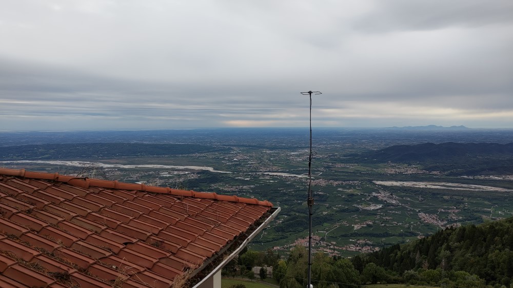
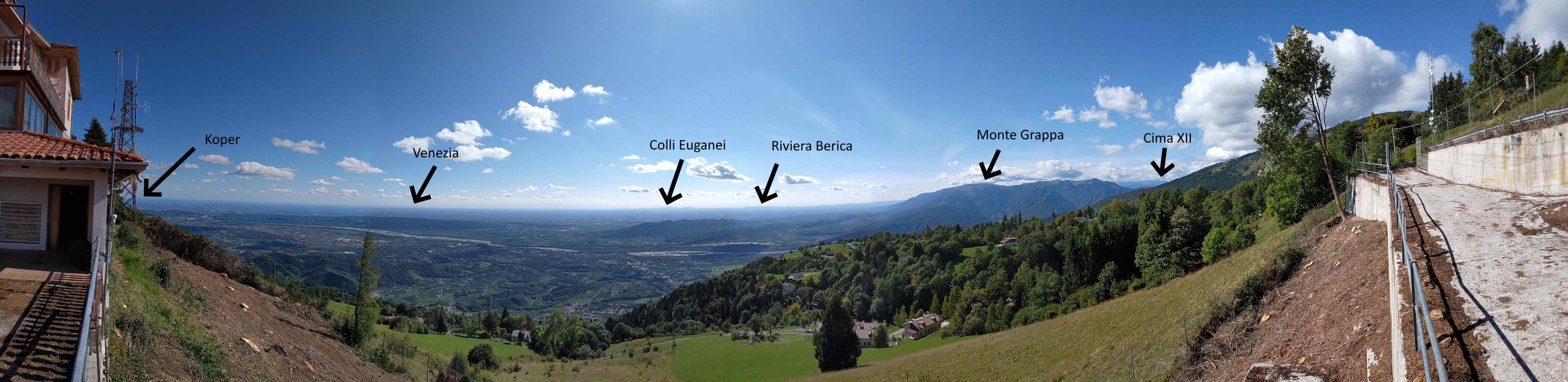
Now the beacon has been installed in it’s final position, on Mt. Cesen, overlooking the famous UNESCO protected Prosecco Hills. The take off from the antenna stack is very good. Looking from 1100 mtrs a.s.l. you can see the adriatic sea in a clear day, from Trieste gulf down to the adriatic, the Pianura Padana right up to Mt. Grappa.
Reports have arrived from all parts of Italy, the DX from Brindisi, down in Puglia, at 760 Km, hrd down to 5 mW.